No products in the cart.


Enjoy Our Daily Deals
20%
Hurry up offer ends in:

Memory, Raspberry Pi
SDSDQAD-016G, 16GB uSD Card un-programmed
Product description
Providing you the high capacity to meet the needs of today’s business professional. Whether you are stuck in an airport or taking a taxi to your next big pitch, SanDisk mobile memory cards enable you to meet deadlines by plugging your files directly into most phones with a microSD card slot, providing convenience and reliability. Class 4 Speed performance rating.
SKU: SWB04003

PIMORONI STORE
RV3028 REAL TIME CLOCK (RTC) BREAKOUT
An ultra-low-power ( ~100 nA), highly accurate real-time clock breakout. The RV3028 RTC breakout?is perfect for adding timekeeping to your project and, thanks to the tiny on-board battery, it’ll keep time when your device is powered off. Like all the best timepieces, it’s Swiss-made!
SKU: PIM449

PIMORONI STORE
BLINKT
Features
Eight APA102 RGB LEDs
Individually controllable pixels
Sits directly on top of your Pi in a tiny footprint
Fits inside most Pi cases
Doesn’t interfere with PWM audio
Compatible with all 40-pin header Raspberry Pi models
Comes fully assembled
Software
Our?Blinkt! Python library?will have you blasting out rainbows in two shakes of a unicorn’s tail! There’s a stack of examples too, from binary clocks to cheerlights and flickering candles to Larson scanners!
Notes
Be careful to plug in your Blinkt! the correct way round, it has curves on the top that match the corners of your Raspberry Pi
If you want to access the rest of the GPIO at the same time as using Blinkt! then our?Mini Black HAT Hack3r?is the ideal accompaniment, allowing you to combine Blinkt! with another HAT or pHAT, or just prototype using the GPIO pins for your own project
The dimensions of Blinkt! are 65mm long x 8mm wide x 8.5mm thick (thickness includes header and pixels)
Additional accessories shown in photos not included
We featured Blinkt! on a special episode of Bilge Tank where we tried to come up with as many different code examples as possible in one morning.
SKU: PIM184

PIMORONI STORE
BADGER 2040-BADGER ONLY
RP2040 x e Ink?
We’re?big fans of electronic paper?at Pirate HQ – it makes for a lovely, crisp, high contrast display that’s readable even in bright sunlight and it doesn’t squirt unnecessary blue light into your environs like LCDs do. It’s also ultra low power (EPD displays only consume power while they’re refreshing), and the images on the display stick around for a really long time whilst the display is unpowered.
Using a RP2040 chip means we can drive the hardware in fun, experimental, low level ways. We’ve written custom drivers for the EPD display that prioritise low power consumption whilst enabling lightning fast refresh rates.
Features
2.9″ black and white E Ink? display (296 x 128 pixels)
Ultra wide viewing angles
Ultra low power consumption
Dot pitch – 0.227 x 0.226 mm
Powered by RP2040 (Dual Arm Cortex M0+ running at up to 133Mhz with 264kB of SRAM)
2MB of QSPI flash supporting XiP
Five front user buttons
Reset and boot buttons (the boot button can also be used as a user button)
White LED
USB-C connector for power and programming
JST-PH connector for attaching a battery (input range 2.7V – 6V)
High-precision voltage reference for battery level monitoring
Qw/ST (Qwiic/STEMMA QT) connector
Fully-assembled (no soldering required)
SKU: PIM607

PIMORONI STORE
BADGER 2040-BADGER+ACCESSORY KIT
Badger + Accessory Kit includes
Badger 2040
2 x AAA battery holder
2 x AAA batteries
Velcro square
Black lanyard (made from recycled plastic bottles!)
USB-C to USB-A cable
Software
Because it’s a RP2040 board, Badger 2040 is firmware agnostic! You can program it with C/C++, MicroPython or CircuitPython.
Our?C++/MicroPython?libraries contain some nifty software tweaks to let you get the most out of your Badger. You’ll get best performance using C++, but if you’re a beginner we’d recommend using our batteries included MicroPython build for ease of getting started.
You can also use?CircuitPython?on your Badger 2040. CircuitPython drivers are designed to work on a bunch of different microcontrollers so you won’t get the fancy RP2040-architecture specific tweaks that you’ll find in our library, but you will get access to all the nice conveniences of Adafruit’s ecosystem.
Connecting Breakouts
If your breakout has a QW/ST connector on board, you can plug it straight in with a?JST-SH to JST-SH cable, or you can easily connect any of our I2C Breakout Garden breakouts with a?JST-SH to JST-SH cable?coupled with a?Qw/ST to Breakout Garden adaptor.
List of breakouts?currently compatible with our C++/MicroPython build.
Printables
Want to protect Badger from knocks and scrapes? Check out these nifty 3D printable cases and enclosures!
Badger Guard?(simple backplate with standoffs)
Badger 2040 stand?by samuelmcdermott
Case for Pimoroni Badger 2040?by hsavior
Badger 2040 enclosure?by?Andreas K?nner
Badger 2040 keypad?by?Andreas K?nner
Notes
Measurements: 85.6mm x 48.7mm x 10mm (L x W x H, including connectors). The mounting holes are M2 and 2.9mm in from each edge. The corner radius is 3mm.
Badger 2040 is fairly accommodating about input voltage (2.7V – 6V), so it’s possible to use a variety of different batteries and battery packs. A?2x AAA battery pack?fits behind Badger nicely (double/triple AA and AAA battery packs will also work though).
2x AAA?rechargeable (NiMH) batteries?only puts out 2.4V which is, strictly speaking, not enough for Badger. However, in our tests it keeps on truckin’ down to an input voltage of 2.05V (without the LED), so if you want to use rechargeable batteries that should be fine.
Alternatively, you can plug a?LiPo/LiIon battery?into the battery connector, with the following caveats. Please only consider this if the person wearing the badge is an adult and knows what they’re doing with LiPos!
A solid enclosure or backplate to protect the battery from damage whilst being worn is a very good idea.
There’s no battery protection included on Badger 2040, so you should only use it with LiPo batteries that include internal protection (all ours do).
Unlike some of our other boards, Badger 2040 doesn’t have battery charging circuitry onboard. You’ll need an external LiPo charger to charge the battery (like a?LiPo Amigo).
With older versions of the Badger firmware, reset behaviour?is slightly different when running on battery. If you’re running on battery power, you will need to?tap?the reset button on the back, and then?hold any of the front buttons?to wake it up and trigger a refresh. With?version 1.18.5?or later of the Badger firmware you won’t need to do this.
SKU: PIM610

PIMORONI STORE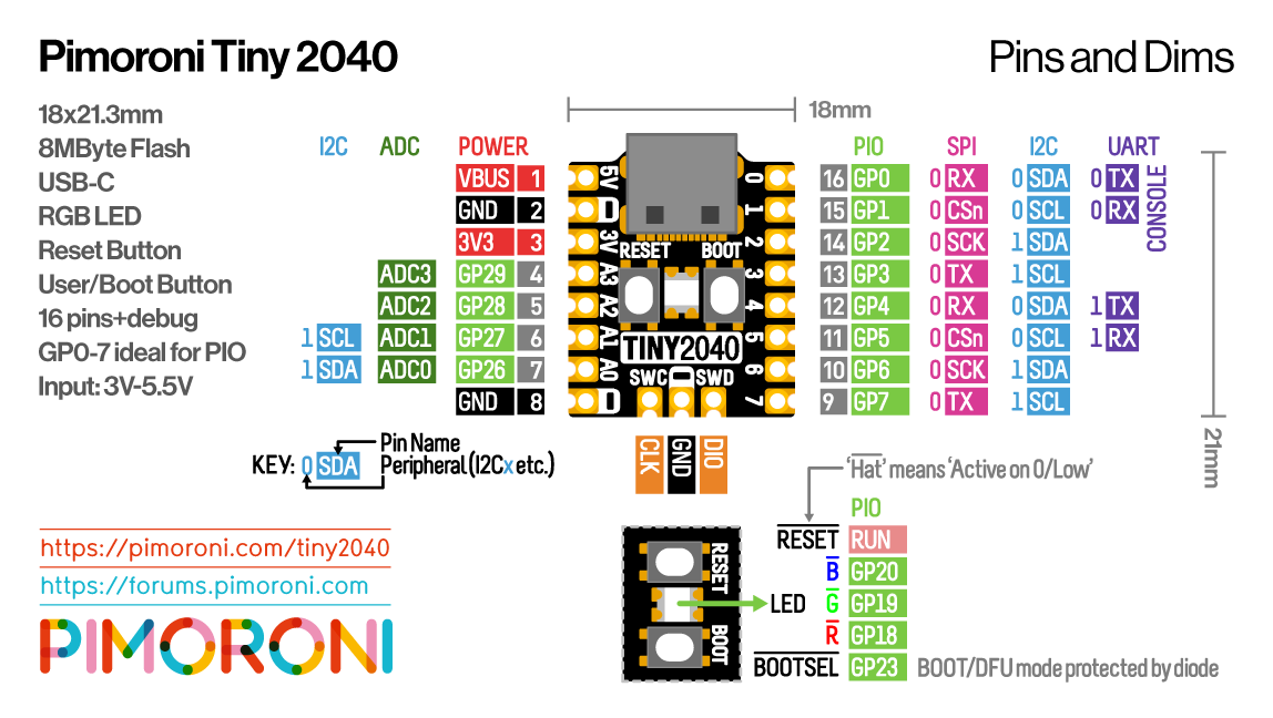
TINY 2040-2MB
Features
Powered by RP2040
ARM Cortex M0+ running at up to 133Mhz
264kB of SRAM
USB-C connector for power, programming, and data transfer
2MB or 8MB of QSPI flash supporting XiP
User controllable RGB LED
Twelve IO pins (including four 12-bit ADC channels)
Switch for basic input (doubles up as DFU select on boot)
On-board 3V3 regulator (max regulator current output 300mA)
Input voltage range 3V – 5.5V
Dimensions: approx 22.9 x 18.2 x 6mm (L x W x H, including the USB-C port)
Schematic?(8MB)
Getting Started
Tiny 2040 is firmware agnostic! You can program it with?C/C++ or MicroPython?in the same way as you would a Raspberry Pi Pico, though you’ll need to bear in mind that it has a reduced number of pins. You can find (lots) more information on how to do that (as well as download links for the firmware/SDK) on the?RP2040 landing page.
You can also use?CircuitPython?on your Tiny 2040! CircuitPython is an easy to use, well-established ecosystem with lots of example code and drivers for interfacing with different kinds of hardware.
Notes
The RGB LED is connected to GP18-GP20 and?active low?(so the on/off state will work in the opposite way to the LED on a Raspberry Pi Pico). You can PWM the pins to dim the LED – check out?Tonygo2’s MicroPython example.
About RP2040
Raspberry Pi’s RP2040 microcontroller is a dual core ARM Cortex M0+ running at up to 133Mhz. It bundles in 264kB of SRAM, 30 multifunction GPIO pins (including a four channel 12-bit ADC), a heap of standard peripherals (I2C, SPI, UART, PWM, clocks, etc), and USB support.
One very exciting feature of RP2040 is the programmable IOs which allow you to execute custom programs that can manipulate GPIO pins and transfer data between peripherals – they can offload tasks that require high data transfer rates or precise timing that traditionally would have required a lot of heavy lifting from the CPU.
SKU: PIM593

PIMORONI STORE
PLASMA 2040
Features
Powered by RP2040 (Dual Arm Cortex M0+ running at up to 133Mhz with 264kB of SRAM)
2MB of QSPI flash supporting XiP
Compatible with 5V WS2812/Neopixel/SK6812 and APA102/Dotstar/SK9822 LEDs
Screw terminals for attaching your LED strip.
USB-C connector for power and programming (3A max)
Qw/ST (Qwiic/STEMMA QT) connector
Low side current sensing (accessible via ADC3)
Reset, BOOT and two user buttons (the BOOT button can also be used as a user button)
RGB LED
Fully-assembled (no soldering required)
Measurements: approx 50 x 28 x 12mm (L x W x H, including connectors)
LED strip and connectors are sold separately, check out the extras tab for some options!
Getting Started
Plasma 2040 is firmware agnostic! You can program it with C/C++ or MicroPython in the same way as you would a Raspberry Pi Pico. You can find (lots) more information on how to do that (as well as download links for the firmware/SDK) on the?RP2040 landing page. You can find documentation for our MicroPython Plasma module?here.
You can also use CircuitPython on your Plasma 2040! CircuitPython is an easy to use, well-established ecosystem with lots of example code and drivers for interfacing with different kinds of hardware.?Click here?to download the CircuitPython firmware for Plasma 2040 and?click here?for a getting started guide.
Click?here?for a beginner friendly tutorial that covers how to hook up different kinds of LEDs to Plasma 2040 and how to use it to build a simple busy light. It includes both MicroPython and CircuitPython code!
Connecting Breakouts
If your breakout has a QW/ST connector on board, you can plug it straight in with a?JST-SH to JST-SH cable, or you can easily connect any of our I2C breakouts with a?JST-SH to JST-SH cable?coupled with a?Qw/ST to Breakout Garden adaptor.
You can find a list of which breakouts are currently compatible with our C++/MicroPython build?here.
We’ve also broken out a set of I2C pins, analog pins and debug pins so you can solder things like breakouts or analog potentiometers directly to them (or solder on a strip of header and plug the whole shebang into a breadboard).
Notes
Our C++/MicroPython software uses the RP2040’s PIO state machines to drive each strip separately – this board only has one set of LED strip connectors, but if you’re up for some inventive wiring it’s possible to drive multiple strips simultaneously, even if they’re of different types!
If you’re curious about how much current your LEDs are consuming, we’ve incorporated some current sensing circuitry onto this board, which you can measure by reading ADC3. You could use this in your code to do things like adjusting the brightness of your LEDs based on available power!
About RP2040
Raspberry Pi’s RP2040 microcontroller is a dual core ARM Cortex M0+ running at up to 133Mhz. It bundles in 264kB of SRAM, 30 multifunction GPIO pins (including a four channel 12-bit ADC), a heap of standard peripherals (I2C, SPI, UART, PWM, clocks, etc), and USB support.
One very exciting feature of RP2040 is the programmable IOs which allow you to execute custom programs that can manipulate GPIO pins and transfer data between peripherals – they can offload tasks that require high data transfer rates or precise timing that traditionally would have required a lot of heavy lifting from the CPU.
SKU: PIM582

PIMORONI STORE
BME688 4-IN-1 QUALITY BREAKOUT(GAS TEMPERATURE,PRESSURE, HUMIDITY))
Features
Bosch BME688 4-in-1 environmental sensor with Artificial Intelligence (datasheet)
I2C interface, with address select via ADDR cuttable trace (0x76 or 0x77)
Qwiic/STEMMA QT connector
3.3V or 5V compatible
Reverse polarity protection (on Breakout Garden connector)
Raspberry Pi-compatible pinout (pins 1, 3, 5, 7, 9)
Compatible with Arduino
Compatible with Raspberry Pi (Python library)
Compatible with Raspberry Pi Pico (C++/MicroPython libraries)
Kit includes
BME688 breakout
1×5 male header
1×5 female right angle header
We’ve designed this breakout board so that you can solder on the piece of right angle female header and pop it straight onto the bottom left 5 pins on your Raspberry Pi’s GPIO header (pins 1, 3, 5, 7, 9). The right angle header also has the advantage of positioning the breakout away from the Pi’s CPU so as to minimise radiated heat.
Software
Bosch provide a C library,for this sensor, but we’ve also updated our BME680?Python library?(with a quick and painless one-line-installer) to work with the BME688, making it straightforward to combine it with our other boards (why not use a Blinkt! or Unicorn pHAT to visualise air quality in real time?)
You can also use this breakout with Raspberry Pi Pico and other?RP2040 boards,?using?C++?or Pirate brand MicroPython.
Notes
In our testing, we’ve found that the sensor requires some burn-in time (at least 20 minutes) and that readings may take a couple of minutes to stabilise after beginning measurements
The trace on the back of the board marked ADDR can be cut to change the I2C address from the default of 0x76 to 0x77, meaning that you can use up to two sensors on the same Raspberry Pi or Arduino
The BME280, BME680, BMP280 and BME688 breakouts all share the same I2C addresses, so if you’re using two together then you’ll need to change the I2C address on one of them using the solder bridge or cuttable traces.
Dimensions: approx 19mm x 19mm x 5mm (L x W x H, including connector)
SKU: PIM575

PIMORONI STORE
BME280 BREAKOUT-TEMPERATURE,PRESSURE HUMIDITY SENSOR)
Features
Bosch BME280 temperature, pressure, humidity sensor (datasheet)
I2C interface, with address select via cuttable ADDR trace (0x76 or 0x77)
Qwiic/STEMMA QT connector
3.3V or 5V compatible
Reverse polarity protection (on Breakout Garden connector)
Raspberry Pi-compatible pinout (pins 1, 3, 5, 7, 9)
Compatible with Arduino
Compatible with Raspberry Pi (Python library)
Compatible with Raspberry Pi Pico (C++/MicroPython libraries)
Kit includes
BME280 breakout
1×5 male header
1×5 female right angle header
We’ve designed this breakout board so that you can solder on the piece of right angle female header and pop it straight onto the bottom left 5 pins on your Raspberry Pi’s GPIO header (pins 1, 3, 5, 7, 9). The right angle header also has the advantage of positioning the breakout away from the Pi’s CPU so as to minimise radiated heat.
Software
We’ve put together a?Python library?for using the BME280 sensor with a Raspberry Pi, with handy functions to read all of the values, and?a few nice little examples.
You can also use this breakout with Raspberry Pi Pico and other RP2040 boards, using?C++ or Pirate brand MicroPython?or?CircuitPython.
Notes
In our testing, we’ve found that the sensor requires some burn-in time (at least 20 minutes) and that readings may take a couple of minutes to stabilise after beginning measurements
The trace on the back (marked ADDR) can be cut to change the I2C address from the default of 0x76 to 0x77, meaning that you can use up to two sensors on the same Raspberry Pi or Arduino.
The BME280, BME680, and BMP280 breakouts all share the same I2C addresses, so if you’re using two together then you’ll need to change the I2C address on one of them using the cuttable trace.
Dimensions: 19x19x4.7mm (LxWxH, including connectors)
SKU: PIM472

PIMORONI STORE
Interstate 75 – RGB LED Matrix Driver
LED matrix panels and cables are sold separately, check out the extras tab for some options!
Software
Because it’s a RP2040 board, Interstate 75 is firmware agnostic! You can program it with C/C++, MicroPython or CircuitPython.
Our?C++/MicroPython?libraries contain some spiffy HUB75 drivers that use RP2040’s PIO state machines and DMA to minimise CPU usage and maximise luscious, 10-bit gamma corrected colour depth.
You’ll get best performance using C++, but if you’re a beginner we’d recommend using our batteries included MicroPython build for ease of getting started.
You can also use?CircuitPython?on your Interstate 75! Because CircuitPython drivers are designed to work on a bunch of different microcontrollers you won’t get the fancy RP2040-architecture specific tweaks that you’ll find in our library, but you will get access to Adafruit’s mighty DisplayIO library which makes it super easy to display all sorts of different kinds of text, draw shapes and display images.
Please note that some less-common varieties of 64×64 panels, like ones that use the FM6126A chip, are not currently supported in CircuitPython.
Connecting Breakouts
If your breakout has a QW/ST connector on board, you can plug it straight in with a?JST-SH to JST-SH cable, or you can easily connect any of our I2C Breakout Garden breakouts with a?JST-SH to JST-SH cable?coupled with a?Qw/ST to Breakout Garden adaptor.
You can find a list of which breakouts are currently compatible with our C++/MicroPython build in the most recent?release notes.
We’ve also broken out a bunch of useful I2C pins, analog pins and debug pins along the side of the board so you can solder things like breakouts or analog potentiometers directly to them.
About RP2040
Raspberry Pi’s RP2040 microcontroller is a dual core ARM Cortex M0+ running at up to 133Mhz. It bundles in 264kB of SRAM, 30 multifunction GPIO pins (including a four channel 12-bit ADC), a heap of standard peripherals (I2C, SPI, UART, PWM, clocks, etc), and USB support.
One very exciting feature of RP2040 is the programmable IOs which allow you to execute custom programs that can manipulate GPIO pins and transfer data between peripherals – they can offload tasks that require high data transfer rates or precise timing that traditionally would have required a lot of heavy lifting from the CPU.
SKU: PIM584

PIMORONI STORE
PICO PROTO
Your Pico will need to have male headers soldered to it?(with the pins pointing downwards) to attach to our add-on boards.
Features
40 2.54mm spaced holes for attaching to your Pico.
120 2.54mm spaced holes (6×20 grid) for attaching other things
Compatible with Raspberry Pi Pico.
Dimensions: approx 51mm x 25mm x 1mm (L x W x H)
SKU: PIM554
Embedded Development Kits & Accessories, Fans & Blowers, Heat Sinks, Raspberry Pi
Case Fan & heatsink for Raspberry Pi 4 Case
Embedded Development Kits & Accessories, Fans & Blowers, Heat Sinks, Raspberry Pi
Case Fan & heatsink for Raspberry Pi 4 Case
Fitting instructions
1 Remove any SD card, then put your Raspberry Pi into the lower half (base)
of the case. Take care to align the mounting holes in the corners with the
bumps in the case.
2 Insert the fan into the upper half (lid) of the case, with the green label facing
away from the lid. Push gently but firmly so that the two tabs on the fan
housing click neatly into place inside the tabs on the lid. The slightly curved
edge of the housing should be flush with the underside of the lid.
3 If you are also fitting the heatsink, remove the backing paper from the
self-adhesive pad on the base of the heatsink, position it centrally over the
processor, and gently press it into position.
4 Connect the three leads from the fan to the Raspberry Pi 4?s GPIO pins, as
shown in the table and diagram below. Take care to connect each lead to the
correct pin.
Lead Colour GPIO pin
5v RED 4
Ground BLACK 6
GPIO 14 BLUE 8
5 Fit the lid of the case onto the base.
WARNINGS
? This product should only be used in conjunction with Raspberry Pi 4 Model B and the official Raspberry
Pi 4 Case.
? This product should be operated in a well-ventilated environment and the case should not be covered.
SAFETY INSTRUCTIONS
To avoid malfunction or damage to this product, please observe the following:
? Do not expose to water or moisture, or place on a conductive surface whilst in operation.
? Do not expose to heat from any external source; the Raspberry Pi Case Fan is designed for reliable
operation at normal ambient temperatures.
? Take care whilst handling to avoid mechanical or electrical damage to the fan and connectors.
? Avoid handling the fan whilst it is powered.
SKU: SC0448
Latest Products
Showcasing the latest technology
Development Tools, Software & Embedded Computers, Raspberry Pi, RASPBERRY PI STORE
Raspberry Pi 5
Specification
Processor Broadcom BCM2712 2.4GHz quad-core 64-bit Arm Cortex-A76 CPU,
with cryptography extensions, 512KB per-core L2 caches, and a
2MB shared L3 cache
Features: • VideoCore VII GPU, supporting OpenGL ES 3.1, Vulkan 1.2
• Dual 4Kp60 HDMI® display output with HDR support
• 4Kp60 HEVC decoder
• LPDDR4X-4267 SDRAM
(4GB and 8GB SKUs available at launch)
• Dual-band 802.11ac Wi-Fi®
• Bluetooth 5.0 / Bluetooth Low Energy (BLE)
• microSD card slot, with support for high-speed SDR104 mode
• 2 × USB 3.0 ports, supporting simultaneous 5Gbps operation
• 2 × USB 2.0 ports
• Gigabit Ethernet, with PoE+ support
(requires separate PoE+ HAT)
• 2 × 4-lane MIPI camera/display transceivers
• PCIe 2.0 x1 interface for fast peripherals
(requires separate M.2 HAT or other adapter)
• 5V/5A DC power via USB-C, with Power Delivery support
• Raspberry Pi standard 40-pin header
• Real-time clock (RTC), powered from external battery
• Power button
SKU: n/a
Uncategorized
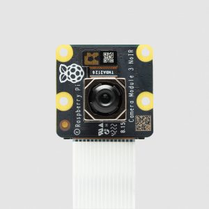
Camera Module 3 NoIR
Specification
Sensor: Sony IMX708
Resolution: 11.9 megapixels
Sensor size: 7.4mm sensor diagonal
Pixel size: 1.4μm × 1.4μm
Horizontal/vertical: 4608 × 2592 pixels
Common video modes: 1080p50, 720p100, 480p120
Output: RAW10
IR cut filter: Integrated in standard variants; not present in NoIR variants
Autofocus system: Phase Detection Autofocus
Dimensions: 25 × 24 × 11.5mm (12.4mm height for Wide variants)
Ribbon cable length: 200mm
Cable connector: 15 × 1mm FPC
Compliance: FCC 47 CFR Part 15, Subpart B, Class B Digital Device
Electromagnetic Compatibility Directive (EMC) 2014/30/EU
Restriction of Hazardous Substances (RoHS) Directive
2011/65/EU
Production lifetime: Raspberry Pi Camera Module 3 will remain in production until
at least January 2030
SKU: n/a

Arduino, Arduino
Arduino Starter Kit
Tech specs
The Starter Kit includes:
1 Projects Book (170 pages),
1 Arduino Uno,
1 USB cable,
1 Breadboard 400 points,
70Solid core jumper wires,
1 Easy-to-assemble wooden base,
1 9v battery snap,
1 Stranded jumper wires (black),
1 Stranded jumper wires (red),
6 Phototransistor,
3 Potentiometer 10kOhms,
10Pushbuttons,
1 Temperature sensor [TMP36],
1 Tilt sensor,
1 alphanumeric LCD (16×2 characters),
1LED (bright white),
1 LED (RGB),
8 LEDs (red),
8 LEDs (green),
8 LEDs (yellow),
3 LEDs (blue),
1 Small DC motor 6/9V,
1 Small servo motor,
1 Piezo capsule [PKM22EPP-40],
1 H-bridge motor driver [L293D],
1 Optocouplers [4N35],
2 Mosfet transistors [IRF520],
3 Capacitors 100uF,
5 Diodes [1N4007],
3 Transparent gels (red, green, blue),
1 Male pins strip (40×1),
20 Resistors 220 Ohms,
5Resistors 560 Ohms,
5 Resistors 1 kOhms,
5 Resistors 4.7 kOhms,
20 Resistors 10 kOhms,
5Resistors 1 MOhms,
5 Resistors 10 MOhms
SKU: n/a

Arduino, Arduino
Arduino Zero
Tech specs
| Microcontroller | ATSAMD21G18, 32-Bit ARM® Cortex® M0+ |
| Operating Voltage | 3.3V |
| Digital I/O Pins | 20 |
| PWM Pins | 3, 4, 5, 6, 8, 9, 10, 11, 12, 13 |
| UART | 2 (Native and Programming) |
| Analog Input Pins | 6, 12-bit ADC channels |
| Analog Output Pins | 1, 10-bit DAC |
| External Interrupts | All pins except pin 4 |
| DC Current per I/O Pin | 7 mA |
| Flash Memory | 256 KB |
| SRAM | 32 KB |
| EEPROM | None. See documentation |
| LED_BUILTIN | 13 |
| Clock Speed | 48 MHz |
| Length | 68 mm |
| Width | 53 mm |
| Weight | 12 gr. |
SKU: n/a

Arduino, Arduino
Arduino Nano 33 BLE
Tech specs
The Arduino Nano 33 BLE is based on the nRF52840 microcontroller.
| Microcontroller | nRF52840 (datasheet) |
| Operating Voltage | 3.3V |
| Input Voltage (limit) | 21V |
| DC Current per I/O Pin | 15 mA |
| Clock Speed | 64MHz |
| CPU Flash Memory | 1MB (nRF52840) |
| SRAM | 256KB (nRF52840) |
| EEPROM | none |
| Digital Input / Output Pins | 14 |
| PWM Pins | all digital pins |
| UART | 1 |
| SPI | 1 |
| I2C | 1 |
| Analog Input Pins | 8 (ADC 12 bit 200 ksamples) |
| Analog Output Pins | Only through PWM (no DAC) |
| External Interrupts | all digital pins |
| LED_BUILTIN | 13 |
| USB | Native in the nRF52840 Processor |
| Length | 45 mm |
| Width | 18 mm |
| Weight | 5 gr (with headers) |
SKU: n/a

Arduino, Arduino
Arduino Nano 33 IoT
WiFi and Arduino IoT Cloud
At Arduino we have made connecting to a WiFi network as easy as getting an LED to blink. You can get your board to connect to any kind of existing WiFi network, or use it to create your own Arduino Access Point. The specific set of examples we provide for the Nano 33 IoT can be consulted at the WiFiNINA library reference page.
It is also possible to connect your board to different Cloud services, Arduino’s own among others. Here some examples on how to get the Arduino boards to connect to:
Arduino’s own IoT Cloud: Arduino’s IoT Cloud is a simple and fast way to ensure secure communication for all of your connected Things. Check it out here
Blynk: a simple project from our community connecting to Blynk to operate your board from a phone with little code
IFTTT: see an in-depth case of building a smart plug connected to IFTTT
AWS IoT Core: we made this example on how to connect to Amazon Web Services
Azure: visit this github repository explaining how to connect a temperature sensor to Azure’s Cloud
Firebase: you want to connect to Google’s Firebase, this Arduino library will show you how
Note: while most of the above-shown examples are running on the MKR WiFi 1010, both boards have the same processor and wireless chipset, which means it will be possible to replicate them with the Nano 33 IoT.
Bluetooth® and Bluetooth® Low Energy
The communications chipset on the Nano 33 IoT can be both a Bluetooth® and Bluetooth® Low Energy client and host device. Something pretty unique in the world of microcontroller platforms. If you want to see how easy it is to create a Bluetooth® central or a peripheral device, explore the examples at our ArduinoBLE library.
We Make it Open for you to Hack Along
The Nano 33 IoT is a dual processor device that invites for experimentation. Hacking the WiFiNINA module allows you to, for example, make use of both WiFi and Bluetooth® and Bluetooth® Low Energy at once on the board. Yet another possibility is having a super-lightweight version of linux running on the module, while the main microcontroller controls low level devices like motors, or screens. These experimental techniques, require advanced hacking on your side. They are possible via modifying the module’s firmware that you can find at our github repositories.
BEWARE: this kind of hacking breaks the certification of your WiFiNINA module, do it at your own risk.
Related Boards
If you are looking at upgrading from previous Arduino designs, or if you are just interested in boards with similar functionality, at Arduino you can find:
Arduino MKR WiFi 1010: the Pro version of the Nano 33 IoT, lacks the accelerometer, but includes a battery charger, and the Arduino Eslov connector for external I2C boards. Read more here.
Arduino Uno WiFi rev2: the education version of the MKR WiFi 1010, with USB-B connector and embedded accelerometer. Read more here.
MKR WiFi 1000: can only run WiFi applications, as it includes a different chipset than the Nano 33 IoT. Read more about it here.
Getting Started
The Getting Started section contains all the information you need to configure your board, use the Arduino Software (IDE), and start tinkering with coding and electronics.
Need Help?
Check the Arduino Forum for questions about the Arduino Language, or how to make your own Projects with Arduino. Need any help with your board please get in touch with the official Arduino User Support as explained in our Contact Us page.
Warranty
You can find here your board warranty information.
Tech specs
The Arduino Nano 33 IoT is based on the SAMD21 microcontroller.
| Microcontroller | SAMD21 Cortex®-M0+ 32bit low power ARM MCU (datasheet) |
| Radio module | u-blox NINA-W102 (datasheet) |
| Secure Element | ATECC608A (datasheet) |
| Operating Voltage | 3.3V |
| Input Voltage (limit) | 21V |
| DC Current per I/O Pin | 7 mA |
| Clock Speed | 48MHz |
| CPU Flash Memory | 256KB |
| SRAM | 32KB |
| EEPROM | none |
| Digital Input / Output Pins | 14 |
| PWM Pins | 11 (2, 3, 5, 6, 9, 10, 11, 12, 16 / A2, 17 / A3, 19 / A5) |
| UART | 1 |
| SPI | 1 |
| I2C | 1 |
| Analog Input Pins | 8 (ADC 8/10/12 bit) |
| Analog Output Pins | 1 (DAC 10 bit) |
| External Interrupts | All digital pins (all analog pins can also be used as interrput pins, but will have duplicated interrupt numbers) |
| LED_BUILTIN | 13 |
| USB | Native in the SAMD21 Processor |
| IMU | LSM6DS3 (datasheet) |
| Length | 45 mm |
| Width | 18 mm |
| Weight | 5 gr (with headers) |
SKU: n/a

Arduino, Arduino
Arduino Nano
Overview
The Arduino Nano is a small, complete, and breadboard-friendly board based on the ATmega328 (Arduino Nano 3.x). It has more or less the same functionality of the Arduino Duemilanove, but in a different package. It lacks only a DC power jack, and works with a Mini-B USB cable instead of a standard one.
SKU: n/a
Arduino, Arduino, Embedded Computers, Education & Maker Boards, Other Educational & Maker Boards
Arduino Uno Rev3
Arduino, Arduino, Embedded Computers, Education & Maker Boards, Other Educational & Maker Boards
Arduino Uno Rev3
Tech specs
| Microcontroller | ATmega328P |
| Operating Voltage | 5V |
| Input Voltage (recommended) | 7-12V |
| Input Voltage (limit) | 6-20V |
| Digital I/O Pins | 14 (of which 6 provide PWM output) |
| PWM Digital I/O Pins | 6 |
| Analog Input Pins | 6 |
| DC Current per I/O Pin | 20 mA |
| DC Current for 3.3V Pin | 50 mA |
| Flash Memory | 32 KB (ATmega328P) of which 0.5 KB used by bootloader |
| SRAM | 2 KB (ATmega328P) |
| EEPROM | 1 KB (ATmega328P) |
| Clock Speed | 16 MHz |
| LED_BUILTIN | 13 |
| Length | 68.6 mm |
| Width | 53.4 mm |
| Weight | 25 g |
SKU: n/a

Arduino, Arduino
Arduino Motor Shield Rev3
Power
The Arduino Motor Shield must be powered only by an external power supply. Because the L298 IC mounted on the shield has two separate power connections, one for the logic and one for the motor supply driver. The required motor current often exceeds the maximum USB current rating.
External (non-USB) power can come either from an AC-to-DC adapter (wall-wart) or a battery. The adapter can be connected by plugging a 2.1mm centre-positive plug into the Arduino’s board power jack on which the motor shield is mounted or by connecting the wires that lead the power supply to the Vin and GND screw terminals, taking care to respect the polarities.
To avoid possible damage to the Arduino board on which the shield is mounted, we recommend using an external power supply that provides a voltage between 7 and 12V. If your motor requires more than 9V we recommend that you separate the power lines of the shield and the Arduino board on which the shield is mounted. This is possible by cutting the “Vin Connect” jumper placed on the back side of the shield. The absolute limit for the Vin at the screw terminals is 18V.
The power pins are as follows:
Vin on the screw terminal block is the input voltage to the motor connected to the shield. An external power supply connected to this pin also provides power to the Arduino board on which is mounted. By cutting the “Vin Connect” jumper you make this a dedicated power line for the motor.
GND Ground on the screw terminal block.
The shield can supply 2 amperes per channel, for a total of 4 amperes maximum.
SKU: n/a

Arduino, Arduino, Development Board Enclosures
Arduino Mega 2560 Rev3
Short Description.
Mega 2560 is an exemplary development board dedicated to building extensive applications as compared to other maker boards by Arduino. The board accommodates the ATmega2560 microcontroller, which operates at a frequency of 16 MHz. The board contains 54 digital input/output pins, 16 analogue inputs, 4 UARTs (hardware serial ports), a USB connection, a power jack, an ICSP header, and a reset button.
SKU: n/a

Arduino, Arduino, Other Educational & Maker Boards
Arduino Student Kit
The Arduino Student Kit is a hands-on, step-by-step remote learning starter kit for ages 11+: get started with the basics of electronics, programming, and coding at home. No prior knowledge or experience is necessary as the kit guides you through step by step. Educators can teach their classes remotely using the kits, and parents can use the kit as a homeschool tool for their children to learn at their own pace. Everyone will gain confidence in programming and electronics with guided lessons and open experimentation.
Benefits of the Arduino Student Kit
● Affordable
● Quick and easy to get started with the step-by-step instructions
● No experience necessary for educators, parents or children
● Fun and engaging with real-world projects to work on
● Use the kit at home that students would be using in class
● Help children improve their problem-solving and critical-thinking skills
● Go at the speed of the individual ability
● Increase in confidence with plenty of support
Quick features of the Arduino Student Kit
● Aimed at age 11+
● Each lesson is linked directly to the curriculum
● Teaches the basic concepts of electricity: current, voltage, digital logic, and programming
● Includes basic electronic components to get hands-on with building and coding
● Easy-to-manage storage
● Coding is pre-written and explained so students can understand how the code works
● Find even more project ideas on the Arduino community
● Access nine 90-minute online lessons, two longer projects, and open-source software
● Dedicated support for any questions
● Includes a collection of resources
What’s included?
● The Arduino Student Kit includes:
○ One Arduino Uno
○ One USB cable
○ One board mounting base
○ One multimeter
○ One 9v battery snap
○ One 9V battery
○ 5 red, 5 green, 5 yellow & 5 blue LEDs
○ Five resistors 560 Ω
○ Five resistors 220 Ω
○ One breadboard 400 points
○ One resistor 1kΩ
○ One resistor 10kΩ
○ One Small Servo motor
○ Two potentiometers 10kΩ
○ Two knob potentiometers
○ Two capacitors 100uF
○ Solid core jumper wires
○ Five pushbuttons
○ One phototransistor
○ Two resistors 4.7kΩ
○ One jumper wire black
○ One jumper wire red
○ One temperature sensor
○ One piezo capsule
○ One jumper wire female to male red
○ One jumper wire female to male black
○ Three nuts and bolts
SKU: n/a

Arduino, Arduino
Arduino Nano RP2040 Connect
Features
Raspberry Pi RP2040 Micrcontroller
133MHz 32bit Dual Core Arm® Cortex®-M0+
264kB on-chip SRAM
Direct Memory Access (DMA) controller
Support for up to 16MB of off-chip Flash memory via dedicated QSPI bus
USB 1.1 controller and PHY, with host and device support
8 PIO state machines
Programmable IO (PIO) for extended peripheral support
4 channel ADC with internal temperature sensor, 0.5 MSa/s, 12-bit conversion
SWD Debugging
SWD Debugging
2 on-chip PLLs to generate USB and core clock
40nm process node
Multiple low power mode support USB 1.1 Host/Device
Internal Voltage Regulator to supply the core voltage
Advanced High-performance Bus (AHB)/Advanced Peripheral Bus (APB)
SKU: n/a
Great Deals
Our best offers and savings

Embedded Development Kits & Accessories
PI400 GPIO PROTECTOR
The IO board comes with a 40pin ribbon cable, which is Grey and rainbow colour optional, 40pin black male connector with anti-reverse insertion at one end is to connect the 40pin female connector at the back of the Pi 400, the user can install the daughter board on the IO board.
All of the materials used on this product are RoHS compliant.
SKU: n/a

BOOKS
THE OFFICIAL RASPBERRY PI BEGINNERS GUIDE
252 pages of essential information:
Set up your Raspberry Pi, install its operating system, and start using this tiny, fully functional computer.
Start coding projects, with step-by-step guides using the Scratch 3 and Python programming languages.
Experiment with connecting electronic components and have fun creating amazing projects.
SKU: MAG38

RASPBERRY PI STORE
OFFICIAL RASPBERRY PI 4 DESKTOP KIT ONLY
SPECIFICATIONS
The Raspberry Pi 4 Desktop kit is supplied with:
Raspberry Pi Keyboard & Mouse
Micro HDMI to Standard HDMI (A/M) 1m Cables
Raspberry Pi 15.3W USB-C Power Supply
Raspberry Pi 4 Case
Official Raspberry Pi Beginner’s Guide (English language)
16GB NOOBS with Raspbian microSD card
SKU: SC0400UK
Embedded Development Kits & Accessories, Fans & Blowers, Heat Sinks, Raspberry Pi
Case Fan & heatsink for Raspberry Pi 4 Case
Embedded Development Kits & Accessories, Fans & Blowers, Heat Sinks, Raspberry Pi
Case Fan & heatsink for Raspberry Pi 4 Case
Fitting instructions
1 Remove any SD card, then put your Raspberry Pi into the lower half (base)
of the case. Take care to align the mounting holes in the corners with the
bumps in the case.
2 Insert the fan into the upper half (lid) of the case, with the green label facing
away from the lid. Push gently but firmly so that the two tabs on the fan
housing click neatly into place inside the tabs on the lid. The slightly curved
edge of the housing should be flush with the underside of the lid.
3 If you are also fitting the heatsink, remove the backing paper from the
self-adhesive pad on the base of the heatsink, position it centrally over the
processor, and gently press it into position.
4 Connect the three leads from the fan to the Raspberry Pi 4?s GPIO pins, as
shown in the table and diagram below. Take care to connect each lead to the
correct pin.
Lead Colour GPIO pin
5v RED 4
Ground BLACK 6
GPIO 14 BLUE 8
5 Fit the lid of the case onto the base.
WARNINGS
? This product should only be used in conjunction with Raspberry Pi 4 Model B and the official Raspberry
Pi 4 Case.
? This product should be operated in a well-ventilated environment and the case should not be covered.
SAFETY INSTRUCTIONS
To avoid malfunction or damage to this product, please observe the following:
? Do not expose to water or moisture, or place on a conductive surface whilst in operation.
? Do not expose to heat from any external source; the Raspberry Pi Case Fan is designed for reliable
operation at normal ambient temperatures.
? Take care whilst handling to avoid mechanical or electrical damage to the fan and connectors.
? Avoid handling the fan whilst it is powered.
SKU: SC0448
PIMORONI STORE
PICO PROTO
Your Pico will need to have male headers soldered to it?(with the pins pointing downwards) to attach to our add-on boards.
Features
40 2.54mm spaced holes for attaching to your Pico.
120 2.54mm spaced holes (6×20 grid) for attaching other things
Compatible with Raspberry Pi Pico.
Dimensions: approx 51mm x 25mm x 1mm (L x W x H)
SKU: PIM554
PIMORONI STORE
Interstate 75 – RGB LED Matrix Driver
LED matrix panels and cables are sold separately, check out the extras tab for some options!
Software
Because it’s a RP2040 board, Interstate 75 is firmware agnostic! You can program it with C/C++, MicroPython or CircuitPython.
Our?C++/MicroPython?libraries contain some spiffy HUB75 drivers that use RP2040’s PIO state machines and DMA to minimise CPU usage and maximise luscious, 10-bit gamma corrected colour depth.
You’ll get best performance using C++, but if you’re a beginner we’d recommend using our batteries included MicroPython build for ease of getting started.
You can also use?CircuitPython?on your Interstate 75! Because CircuitPython drivers are designed to work on a bunch of different microcontrollers you won’t get the fancy RP2040-architecture specific tweaks that you’ll find in our library, but you will get access to Adafruit’s mighty DisplayIO library which makes it super easy to display all sorts of different kinds of text, draw shapes and display images.
Please note that some less-common varieties of 64×64 panels, like ones that use the FM6126A chip, are not currently supported in CircuitPython.
Connecting Breakouts
If your breakout has a QW/ST connector on board, you can plug it straight in with a?JST-SH to JST-SH cable, or you can easily connect any of our I2C Breakout Garden breakouts with a?JST-SH to JST-SH cable?coupled with a?Qw/ST to Breakout Garden adaptor.
You can find a list of which breakouts are currently compatible with our C++/MicroPython build in the most recent?release notes.
We’ve also broken out a bunch of useful I2C pins, analog pins and debug pins along the side of the board so you can solder things like breakouts or analog potentiometers directly to them.
About RP2040
Raspberry Pi’s RP2040 microcontroller is a dual core ARM Cortex M0+ running at up to 133Mhz. It bundles in 264kB of SRAM, 30 multifunction GPIO pins (including a four channel 12-bit ADC), a heap of standard peripherals (I2C, SPI, UART, PWM, clocks, etc), and USB support.
One very exciting feature of RP2040 is the programmable IOs which allow you to execute custom programs that can manipulate GPIO pins and transfer data between peripherals – they can offload tasks that require high data transfer rates or precise timing that traditionally would have required a lot of heavy lifting from the CPU.
SKU: PIM584
PIMORONI STORE
BME280 BREAKOUT-TEMPERATURE,PRESSURE HUMIDITY SENSOR)
Features
Bosch BME280 temperature, pressure, humidity sensor (datasheet)
I2C interface, with address select via cuttable ADDR trace (0x76 or 0x77)
Qwiic/STEMMA QT connector
3.3V or 5V compatible
Reverse polarity protection (on Breakout Garden connector)
Raspberry Pi-compatible pinout (pins 1, 3, 5, 7, 9)
Compatible with Arduino
Compatible with Raspberry Pi (Python library)
Compatible with Raspberry Pi Pico (C++/MicroPython libraries)
Kit includes
BME280 breakout
1×5 male header
1×5 female right angle header
We’ve designed this breakout board so that you can solder on the piece of right angle female header and pop it straight onto the bottom left 5 pins on your Raspberry Pi’s GPIO header (pins 1, 3, 5, 7, 9). The right angle header also has the advantage of positioning the breakout away from the Pi’s CPU so as to minimise radiated heat.
Software
We’ve put together a?Python library?for using the BME280 sensor with a Raspberry Pi, with handy functions to read all of the values, and?a few nice little examples.
You can also use this breakout with Raspberry Pi Pico and other RP2040 boards, using?C++ or Pirate brand MicroPython?or?CircuitPython.
Notes
In our testing, we’ve found that the sensor requires some burn-in time (at least 20 minutes) and that readings may take a couple of minutes to stabilise after beginning measurements
The trace on the back (marked ADDR) can be cut to change the I2C address from the default of 0x76 to 0x77, meaning that you can use up to two sensors on the same Raspberry Pi or Arduino.
The BME280, BME680, and BMP280 breakouts all share the same I2C addresses, so if you’re using two together then you’ll need to change the I2C address on one of them using the cuttable trace.
Dimensions: 19x19x4.7mm (LxWxH, including connectors)
SKU: PIM472
PIMORONI STORE
BME688 4-IN-1 QUALITY BREAKOUT(GAS TEMPERATURE,PRESSURE, HUMIDITY))
Features
Bosch BME688 4-in-1 environmental sensor with Artificial Intelligence (datasheet)
I2C interface, with address select via ADDR cuttable trace (0x76 or 0x77)
Qwiic/STEMMA QT connector
3.3V or 5V compatible
Reverse polarity protection (on Breakout Garden connector)
Raspberry Pi-compatible pinout (pins 1, 3, 5, 7, 9)
Compatible with Arduino
Compatible with Raspberry Pi (Python library)
Compatible with Raspberry Pi Pico (C++/MicroPython libraries)
Kit includes
BME688 breakout
1×5 male header
1×5 female right angle header
We’ve designed this breakout board so that you can solder on the piece of right angle female header and pop it straight onto the bottom left 5 pins on your Raspberry Pi’s GPIO header (pins 1, 3, 5, 7, 9). The right angle header also has the advantage of positioning the breakout away from the Pi’s CPU so as to minimise radiated heat.
Software
Bosch provide a C library,for this sensor, but we’ve also updated our BME680?Python library?(with a quick and painless one-line-installer) to work with the BME688, making it straightforward to combine it with our other boards (why not use a Blinkt! or Unicorn pHAT to visualise air quality in real time?)
You can also use this breakout with Raspberry Pi Pico and other?RP2040 boards,?using?C++?or Pirate brand MicroPython.
Notes
In our testing, we’ve found that the sensor requires some burn-in time (at least 20 minutes) and that readings may take a couple of minutes to stabilise after beginning measurements
The trace on the back of the board marked ADDR can be cut to change the I2C address from the default of 0x76 to 0x77, meaning that you can use up to two sensors on the same Raspberry Pi or Arduino
The BME280, BME680, BMP280 and BME688 breakouts all share the same I2C addresses, so if you’re using two together then you’ll need to change the I2C address on one of them using the solder bridge or cuttable traces.
Dimensions: approx 19mm x 19mm x 5mm (L x W x H, including connector)
SKU: PIM575
PIMORONI STORE
PLASMA 2040
Features
Powered by RP2040 (Dual Arm Cortex M0+ running at up to 133Mhz with 264kB of SRAM)
2MB of QSPI flash supporting XiP
Compatible with 5V WS2812/Neopixel/SK6812 and APA102/Dotstar/SK9822 LEDs
Screw terminals for attaching your LED strip.
USB-C connector for power and programming (3A max)
Qw/ST (Qwiic/STEMMA QT) connector
Low side current sensing (accessible via ADC3)
Reset, BOOT and two user buttons (the BOOT button can also be used as a user button)
RGB LED
Fully-assembled (no soldering required)
Measurements: approx 50 x 28 x 12mm (L x W x H, including connectors)
LED strip and connectors are sold separately, check out the extras tab for some options!
Getting Started
Plasma 2040 is firmware agnostic! You can program it with C/C++ or MicroPython in the same way as you would a Raspberry Pi Pico. You can find (lots) more information on how to do that (as well as download links for the firmware/SDK) on the?RP2040 landing page. You can find documentation for our MicroPython Plasma module?here.
You can also use CircuitPython on your Plasma 2040! CircuitPython is an easy to use, well-established ecosystem with lots of example code and drivers for interfacing with different kinds of hardware.?Click here?to download the CircuitPython firmware for Plasma 2040 and?click here?for a getting started guide.
Click?here?for a beginner friendly tutorial that covers how to hook up different kinds of LEDs to Plasma 2040 and how to use it to build a simple busy light. It includes both MicroPython and CircuitPython code!
Connecting Breakouts
If your breakout has a QW/ST connector on board, you can plug it straight in with a?JST-SH to JST-SH cable, or you can easily connect any of our I2C breakouts with a?JST-SH to JST-SH cable?coupled with a?Qw/ST to Breakout Garden adaptor.
You can find a list of which breakouts are currently compatible with our C++/MicroPython build?here.
We’ve also broken out a set of I2C pins, analog pins and debug pins so you can solder things like breakouts or analog potentiometers directly to them (or solder on a strip of header and plug the whole shebang into a breadboard).
Notes
Our C++/MicroPython software uses the RP2040’s PIO state machines to drive each strip separately – this board only has one set of LED strip connectors, but if you’re up for some inventive wiring it’s possible to drive multiple strips simultaneously, even if they’re of different types!
If you’re curious about how much current your LEDs are consuming, we’ve incorporated some current sensing circuitry onto this board, which you can measure by reading ADC3. You could use this in your code to do things like adjusting the brightness of your LEDs based on available power!
About RP2040
Raspberry Pi’s RP2040 microcontroller is a dual core ARM Cortex M0+ running at up to 133Mhz. It bundles in 264kB of SRAM, 30 multifunction GPIO pins (including a four channel 12-bit ADC), a heap of standard peripherals (I2C, SPI, UART, PWM, clocks, etc), and USB support.
One very exciting feature of RP2040 is the programmable IOs which allow you to execute custom programs that can manipulate GPIO pins and transfer data between peripherals – they can offload tasks that require high data transfer rates or precise timing that traditionally would have required a lot of heavy lifting from the CPU.
SKU: PIM582
PIMORONI STORE
TINY 2040-2MB
Features
Powered by RP2040
ARM Cortex M0+ running at up to 133Mhz
264kB of SRAM
USB-C connector for power, programming, and data transfer
2MB or 8MB of QSPI flash supporting XiP
User controllable RGB LED
Twelve IO pins (including four 12-bit ADC channels)
Switch for basic input (doubles up as DFU select on boot)
On-board 3V3 regulator (max regulator current output 300mA)
Input voltage range 3V – 5.5V
Dimensions: approx 22.9 x 18.2 x 6mm (L x W x H, including the USB-C port)
Schematic?(8MB)
Getting Started
Tiny 2040 is firmware agnostic! You can program it with?C/C++ or MicroPython?in the same way as you would a Raspberry Pi Pico, though you’ll need to bear in mind that it has a reduced number of pins. You can find (lots) more information on how to do that (as well as download links for the firmware/SDK) on the?RP2040 landing page.
You can also use?CircuitPython?on your Tiny 2040! CircuitPython is an easy to use, well-established ecosystem with lots of example code and drivers for interfacing with different kinds of hardware.
Notes
The RGB LED is connected to GP18-GP20 and?active low?(so the on/off state will work in the opposite way to the LED on a Raspberry Pi Pico). You can PWM the pins to dim the LED – check out?Tonygo2’s MicroPython example.
About RP2040
Raspberry Pi’s RP2040 microcontroller is a dual core ARM Cortex M0+ running at up to 133Mhz. It bundles in 264kB of SRAM, 30 multifunction GPIO pins (including a four channel 12-bit ADC), a heap of standard peripherals (I2C, SPI, UART, PWM, clocks, etc), and USB support.
One very exciting feature of RP2040 is the programmable IOs which allow you to execute custom programs that can manipulate GPIO pins and transfer data between peripherals – they can offload tasks that require high data transfer rates or precise timing that traditionally would have required a lot of heavy lifting from the CPU.
SKU: PIM593
PIMORONI STORE
BADGER 2040-BADGER+ACCESSORY KIT
Badger + Accessory Kit includes
Badger 2040
2 x AAA battery holder
2 x AAA batteries
Velcro square
Black lanyard (made from recycled plastic bottles!)
USB-C to USB-A cable
Software
Because it’s a RP2040 board, Badger 2040 is firmware agnostic! You can program it with C/C++, MicroPython or CircuitPython.
Our?C++/MicroPython?libraries contain some nifty software tweaks to let you get the most out of your Badger. You’ll get best performance using C++, but if you’re a beginner we’d recommend using our batteries included MicroPython build for ease of getting started.
You can also use?CircuitPython?on your Badger 2040. CircuitPython drivers are designed to work on a bunch of different microcontrollers so you won’t get the fancy RP2040-architecture specific tweaks that you’ll find in our library, but you will get access to all the nice conveniences of Adafruit’s ecosystem.
Connecting Breakouts
If your breakout has a QW/ST connector on board, you can plug it straight in with a?JST-SH to JST-SH cable, or you can easily connect any of our I2C Breakout Garden breakouts with a?JST-SH to JST-SH cable?coupled with a?Qw/ST to Breakout Garden adaptor.
List of breakouts?currently compatible with our C++/MicroPython build.
Printables
Want to protect Badger from knocks and scrapes? Check out these nifty 3D printable cases and enclosures!
Badger Guard?(simple backplate with standoffs)
Badger 2040 stand?by samuelmcdermott
Case for Pimoroni Badger 2040?by hsavior
Badger 2040 enclosure?by?Andreas K?nner
Badger 2040 keypad?by?Andreas K?nner
Notes
Measurements: 85.6mm x 48.7mm x 10mm (L x W x H, including connectors). The mounting holes are M2 and 2.9mm in from each edge. The corner radius is 3mm.
Badger 2040 is fairly accommodating about input voltage (2.7V – 6V), so it’s possible to use a variety of different batteries and battery packs. A?2x AAA battery pack?fits behind Badger nicely (double/triple AA and AAA battery packs will also work though).
2x AAA?rechargeable (NiMH) batteries?only puts out 2.4V which is, strictly speaking, not enough for Badger. However, in our tests it keeps on truckin’ down to an input voltage of 2.05V (without the LED), so if you want to use rechargeable batteries that should be fine.
Alternatively, you can plug a?LiPo/LiIon battery?into the battery connector, with the following caveats. Please only consider this if the person wearing the badge is an adult and knows what they’re doing with LiPos!
A solid enclosure or backplate to protect the battery from damage whilst being worn is a very good idea.
There’s no battery protection included on Badger 2040, so you should only use it with LiPo batteries that include internal protection (all ours do).
Unlike some of our other boards, Badger 2040 doesn’t have battery charging circuitry onboard. You’ll need an external LiPo charger to charge the battery (like a?LiPo Amigo).
With older versions of the Badger firmware, reset behaviour?is slightly different when running on battery. If you’re running on battery power, you will need to?tap?the reset button on the back, and then?hold any of the front buttons?to wake it up and trigger a refresh. With?version 1.18.5?or later of the Badger firmware you won’t need to do this.
SKU: PIM610
Featured Products
Hand picked by our suppliers
Embedded Development Kits & Accessories, Raspberry Pi
Raspberry Pi Mouse (Red/White)
Specification
? Three-button optical mouse
? Scroll wheel
? USB type A connector
? Weight: 105g (110g including packaging)
? Dimensions: 64.12mm ? 109.93mm ? 31.48mm
? (115mm ?75mm ? 33mm including packaging)
SKU: SWB04005

Embedded Development Kits & Accessories, Raspberry Pi
Raspberry Pi Keyboard UK (Red/Whit
Specification:
Keyboard & hub
? 79-key keyboard (78-key keyboard for US model, 83-key keyboard for
Japanese model)
? Three USB 2.0 type A ports for powering other peripherals
? Automatic keyboard language detection
? USB type A to micro USB type B cable included for connection
to compatible computer
? Weight: 269g (376g including packaging)
? Dimensions: 284.80mm 121.61mm ? 20.34mm
? (330mm ? 130mm ? 28mm including packaging)
SKU: SWB04004

Development Board Enclosures, Enclosures, Boxes & Cases, Raspberry Pi
RPI Official Case for Pi4
Specifications
The official Raspberry Pi case for Raspberry Pi 4
High-quality, two-part ABS construction
Cut-outs for the dual micro HDMI, Audio/Video, USB and Ethernet ports, as well as the USB-C power connector and access to the microSD card.
SKU: n/a
Memory, Raspberry Pi
SDSDQAD-016G, 16GB uSD Card un-programmed
Product description
Providing you the high capacity to meet the needs of today’s business professional. Whether you are stuck in an airport or taking a taxi to your next big pitch, SanDisk mobile memory cards enable you to meet deadlines by plugging your files directly into most phones with a microSD card slot, providing convenience and reliability. Class 4 Speed performance rating.
SKU: SWB04003

RASPBERRY PI STORE
Raspberry Pi Pico
The?Raspberry Pi Pico?is an entirely new type of microcontroller from Raspberry Pi. Small, cheap and flexible – it?s great for learning to code with MicroPython!
This is?the standard?Raspberry Pi Pico?- which comes without any?headers??fitted. You can also?purchase our pre-soldered Raspberry Pi Pico here?.
Whether you?re looking to learn about the MicroPython programming language, take your first steps in physical computing or want to build a hardware project, the Raspberry Pi Pico ? and its amazing community ? will support you every step of the way.?We also have a great range of accessories for the Pico too!
SKU: SWB04002
Embedded Development Kits & Accessories, Raspberry Pi
KSA-15E-051300HK official Power Supply, UK UCON 00978
Embedded Development Kits & Accessories, Raspberry Pi
KSA-15E-051300HK official Power Supply, UK UCON 00978
The official Raspberry Pi USB-C power supply is designed to power the latest Raspberry Pi 4 Model B computers, which were released in June 2019. Featuring a captive USB-C cable, the power supply is available in four different models to suit different international power sockets, and in two colours, white and black.
SKU: SWB01001

PIMORONI STORE, Raspberry Pi, RASPBERRY PI STORE
Raspberry Pi 400UK, Unit Only
The?Raspberry Pi 400?is a complete personal computer built into a compact keyboard!
The Pi400 is ideal for learning to code using the Raspberry Pi OS desktop environment and can also be used for a wide range of other activities such as surfing the web, creating and editing documents, watching videos and more!
SKU: SWB02002
RASPBERRY PI STORE
Raspberry Pi 400 Personal Computer Kit
Featuring a quad-core 64-bit processor, 4GB of RAM, wireless networking, dual-display output, and 4K video playback, as well as a 40-pin GPIO header, Raspberry Pi 400 is a powerful, easy-to-use computer built into a neat and portable keyboard.
It?s ideal for learning to code using the Raspberry Pi OS desktop environment and can also be used for a wide range of other activities such as surfing the web, creating and editing documents, watching videos and more!
SKU: SWB02001
Other Embedded Computers, Raspberry Pi, RASPBERRY PI STORE, Single Board Computers
Raspberry Pi 4 Model B
Other Embedded Computers, Raspberry Pi, RASPBERRY PI STORE, Single Board Computers
Raspberry Pi 4 Model B
1.5GHz 64-bit quad-core CPU
Available with 2GB, 4GB or 8GB RAM (select above)
2.4 GHz and 5.0 GHz IEEE 802.11ac wireless, Bluetooth 5.0, BLE
Gigabit Ethernet
2x USB 3.0 ports; 2x USB 2.0 ports.
Raspberry Pi standard 40 pin GPIO header
2 ? micro-HDMI ports (up to 4kp60 supported)
2-lane MIPI DSI display port
2-lane MIPI CSI camera port
4-pole stereo audio and composite video port
265 (4kp60 decode), H264 (1080p60 decode, 1080p30 encode)
OpenGL ES 3.0 graphics
Micro-SD card slot for loading operating system and data storage
5V DC via USB-C connector (minimum 3A*)
5V DC via GPIO header (minimum 3A*)
Power over Ethernet (PoE) enabled (requires separate?PoE HAT?)
SKU: n/a